PIONEER timing belt curvilinear tooth form ensures an optimized load distribution leading to high power transmission in low speed and high torque applications. Applying to the condition of various speed range and high temperature transmission conditions. It has greater advantages than chain drive.
Features
● Strong transmission capacity: can meet the increasing transmission requirements of the machine.
● Better adaptability: meet the requirements of machine working in the severe environment.
● Better driving precision: improve the performance of modern machines.
● Better wear resistance: improve the adaptability to the driving pulleys.
● Longer service life and less noise.
Specification
HTD&STD SYNCHRONOUS BELT | |||||
Section | Pitch (mm) | Tooth Height (mm) | Belt Thickness (mm) | Model Range | |
Min | Max | ||||
2M | 2.00 | 0.75 | 1.36 | 488 | 506 |
3M | 3.00 | 1.17 | 2.40 | 111 | 3000 |
5M | 5.00 | 2.06 | 3.80 | 175 | 3770 |
8M | 8.00 | 3.48 | 6.00 | 112 | 4400 |
14M | 14.00 | 6.02 | 10.00 | 826 | 4578 |
20M | 20 | 8.40 | 13.20 | 2200 | 4200 |
S2M | 2.00 | 0.76 | 1.36 | 120 | 3000 |
S3M | 3.00 | 1.14 | 2.20 | 102 | 3210 |
S5M | 5.00 | 1.91 | 3.40 | 160 | 2765 |
S8M | 8.00 | 3.05 | 5.30 | 376 | 4400 |
S14M | 14.00 | 5.30 | 10.20 | 966 | 3850 |
Applications
Paper and textile machinery, CNC machines, printers, scanners, office machines, Robotic machines, electric hand tools, currency counting machines, food processing machines, etc.
Production Details

The PIONEER synchronous belt is superior timing belts for various types of synchronous drive, with performing on a wide range of load capacities and speed ratios. The belt is non-slip engagement with constant angular velocity, relatively maintenance-free, and economical.
Timing Belt Failure Analysis

Shock Load
Appearance: Snapped
Cause
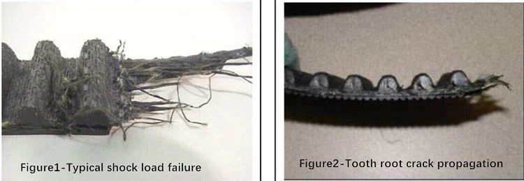
◆ Shock loading in belt drives occurs when higher than normal intermittent or cyclic torque loads are generated by the driven equipment. These shock loads result in higher than normal belt stresses and can act as a catalyst for belt failure.
◆ Severe shock loads can result in belt tensile breaks with a ragged and uneven appearance as illustrated in Figure 4. The particular belt teeth engaged in the sprocket at the instant of the shock load may also develop root cracks and/or exhibit tooth shear.
◆ Figure 5 illustrates how root cracks caused by shock loading can propagate through the teeth. Cracks forming at the tooth roots sometimes move towards the tooth tips. Teeth containing multiple cracks may then shear, leaving only a portion of the tooth behind.
Solutions
If the drive shock loads cannot be eliminated, the belt tensile strength may need to be increased or the synchronous belt drive replaced with a more forgiving V-belt drive system capable of intermittent slip.